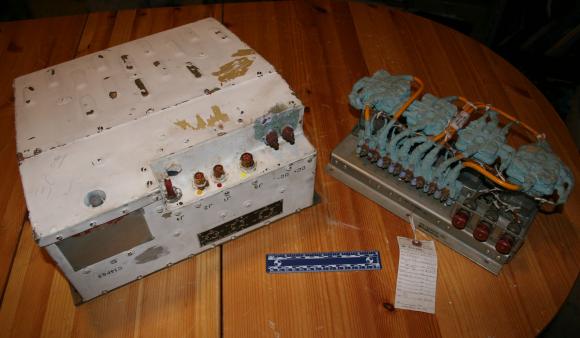
Artifact: Inverter and Motor Control Box, DC to AC, Apollo Command Module, Block II
Copper, Aluminum, Ladicote, Steel
An Apollo Command Module Electrical Power Subsystem Inverter (manufactured by Westinghouse Electric's Aerospace Electrical Division, Lima, Ohio) and an affiliated Inverter DC Control Box (produced by Kinetics Corporation, Solana Beach California). Three of these 53 pound solid-state inverters and one control box were installed in the lower equipment bay; each inverter converted Fuel Cell originated 28 volt Direct Current (DC) to 115-volt Alternating Current (AC), 3 phase 400 Hertz power which was supplied to spacecraft electronics, environmental control system pumps and space suit compressors. The DC Control Box regulated activation of the inverters via motor actuated switching (on/off) of inputted DC voltage from the Command Module's two DC Main Buses "A" and B". At any give time, two of three inverters were online to ensure uninterrupted flow of AC power to the spacecraft.
The inverter is composed of a oscillator, an eight-stage digital countdown section, a dc line filter, two silicon-controlled rectifiers, a magnetic amplifier, a buck-boost amplifier, a demodulator, two dc filters, an eight-stage power inversion section, harmonic neutralization transformer, an ac output filter, current sensing transformers, Zener diode reference bridge, low-voltage control and an overcurrent trip circuit. The inverter normally sourced a 6.4 khz square wave synchronizing signal from the Central Timing Equipment (CTE).
DC voltage from the Fuel Cell powerplants (located in bay IV of the Service Module) was connected to the main DC buses "A" or "B"; Inverter No. 1 powered from DC Main Bus "A", No. 2 by bus "B" and Inverter 3 through either DC Main Bus "A" or "B" by switch selection. Each of the inverters had a separate circuit breaker and power control motor switch (contained within the Inverter DC Control Box). Inverter output was routed (via a separate series of control motor switches) to the Command Module AC buses.

